Offshore - installation - decommission - salvage
- Vessels
- Engines / equipment
- Propulsion engines
- Allen Diesel
- B&W Alpha
- Pegaso Guascor
- MTU
- Iveco Aifo
- Deutz
- Detroit Diesel
- DAF
- Volvo Penta
- Gardner
- Cummins
- Valmet
- MWM
- Bergen Diesel
- Callesen Diesel
- Grenaa Motor Fabrik
- MAN B&W
- Hyundai
- Caterpillar
- Lister-Blackstone
- MaK
- GMT
- Mirrlees Blackstone
- Nohab Polar
- Paxman Diesel
- MAN
- Mitsubishi
- Scania
- Stork Werkspoor
- Wärtsilä
- Stork Wärtsilä
- Yanmar marine engines
- Mercedes marine diesel
- Wizeman marine diesel
- EMD
- Baudouin
- Normo Diesel
- Sulzer
- Ruston
- Ford
- INDUSTRIE
- Crepelle
- WÄRTSILÄ WICHMANN 28
- MWM DITER
- SKL
- Buckau Wolf
- Isuzu
- NOGVA
- John Deere
- marine gearbox
- RAPP FJELLHAMAR
- VOLDA
- FINNØY
- LIAAEN
- MEKANORD
- Lohmann & Stolterfoht
- HYTEK
- KUYPERS Gears
- GUASCOR
- Twin Disc
- Pay & Brinck
- B&W Alpha
- REINTJES
- Ulstein propeller
- Masson Marine
- MIRRLEES BLACKSTONE
- HJELSET
- Heimdal Propulsion
- RENK
- Norgear - Kumera
- Zamech
- Fernholdt & Giertsen
- ZF Marine
- Lister Blackstone
- Rhenania
- Nico
- Engrenages et Reducteurs
- TACKE
- Capitol marine gear
- Korsør
- Callesen gear coupling
- Nogva Heimdal
- SCG Self-Changing Gears
- Generators
- Air compressor
- Offshore - installation - decommission - salvage
- Hydraulic pump
- Water Pumps
- Three Screw Pumps
- Heat exchangers
- Electric motors
- Generator sets
- Ship interior
- Oily water separator
- Transformers
- ELECTRONIC EQUIPMENT
- Hydraulic powerpacks
- Engine Control Systems
- Oil separator
- Governor / actuator
- Deck equipment
- Filter
- Hydraulic motor
- Cooling compressors
- TURBO
- Propulsion engines
- Spare parts
- MTU original spare parts
- Detroit spare parts
- MAN B&W spare parts
- Mak spare parts
- Nohab Polar spare parts
- GMT spare parts
- Deutz spare parts
- B&W Alpha spare parts
- MWM spareparts
- Scania spare parts
- Callesen spare parts
- Electric and Electronic spare parts
- MAR-EL
- Kongsberg Autronica
- Robertson
- Hydraulic Brattvaag
- Ulstein Marine
- PHONTEC
- Penny & Giles
- Elmatic
- AUTO-MASKIN
- HELITRON
- Bosch
- Paab
- Mean well
- Pikotec OY
- Praxis Automation
- Brunvoll
- Saia-Burgess
- Rolls-Royce
- Kongsberg
- Wartsila
- Danica Supply
- Kongsberg KaMeWa
- JRCS
- Emerson
- Vickers
- Polyamp
- KARISMAR
- NORSEligth
- Various electronic spares
- IDEC
- Siemens
- CAREL
- Rexroth
- Leroy-Somer
- Wika
- Phoenix Contact
- Terasaki
- JRC
- Hirschmann
- Beijer Electronics
- ABB
- DEIF
- MGV Stromversorgungen
- Lilley & Gillie
- Fire alarm systems
- TOKIMEC
- SYSLOGIC EUROLOG
- F. K. SMITH AS
- MARINEX
- Intelligent Instrumentation
- Semikron Danfoss
- Vicor Corporation
- Mitsubishi
- O.Øverland AS
- Boolean
- SCHOTTEL
- RHEINTACHO
- SMART Automation
- JUNG-A MARINE
- Lilaas
- lilaas
- Moxa
- TT Electronics
- Merlin Gerin
- Dräger
- SELCO
- TERASAKI
- Denison Hydraulics
- Fuji Electric
- PEP Modular Computers
- Pelco
- FSG Fernsteuergeräte
- Raytheon
- Wago
- Bergen Diesel / ROLLS-ROYCE MARINE Orignial spares
- Volvo spare parts
- Gardner spare parts
- Ruston spares
- L’Orange
- Normo spare parts
- MWM DITER
- Sulzer spares
- Wärtsilä spares
- Yanmar spare parts
- Hatteland Display
- PISTON RINGS
- Roller bearings
- Wichmann spare parts
- MAN Spare Parts
- AMOT
- TURBO
- Subsea noise mitigation
Viewed products
-

Plattform Jacket...
Set of 4 Buoyancy Tanks...
-

SKF 29424 E Spherical...
SKF 29424 E Spherical Roller Thrust...
New products
-

Mitsubishi AL2-14MR-D
Mitsubishi AL2-14MR-D
-

Mitsubishi AL2-2DA
Mitsubishi AL2-2DA
-

TOCOS RA30Y 30S B251 potentiometer
TOCOS RA30Y 30S B251 potentiometer
-

FSG PK 620 - 46 M III d Precision Potentiometer
FSG PK 620 - 46 M III d Precision Potentiometer
-

Yanmar 153605-11350 Bolt M12X265
Yanmar 153605-11350Bolt M12X265
-

Scania DI 12 62M 285 kW @ 1800 RPM
Scania DI 12 62M285 kW @ 1800 RPM
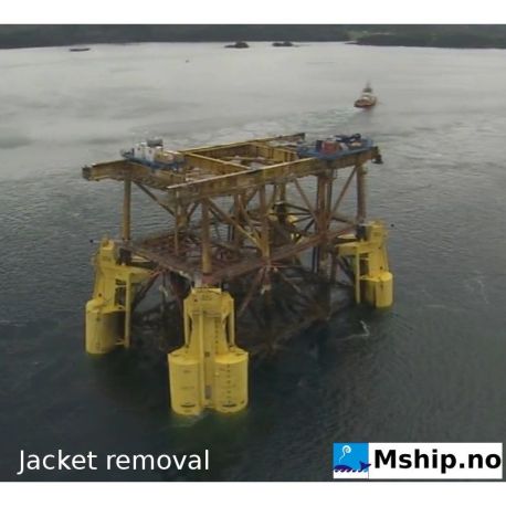
Plattform Jacket decomissioning equipment - Heavy Lift salvage bouys system
BTA
Used
Set of 4 Buoyancy Tanks Assemblies(BTA) for offshore decommissioning or salvage with lifting capacity of 12.000 TON Gross.

Looking for similar equipment ? Click HERE to contact us
Data sheet
| Manufacturer | Aker solutions - Norway |
| Model | BTA DP2 |
| Performance specification | About 12.000 TON lifting capacity. |
| Year | 2008 |
| Class | Documented and DNV certified method for removal of jackets |
More info
Advantages of the Buoyancy Tank Assemblies
Video
• Installation and removal of marine structures can be done without crane lifting capability
• Safe principle of operation with comprehensive systems & operations description
• High total floating capacity
• Documented and DnV certified method for removal of jackets
• Patented technology
• Flexible transit by tow, on barge or by ship
• Unique technology and equipment, the 4 BTAs’ are the only existing ones
Buoyancy Tanks Assemblies (BTA)
Total length of assembly 65 meter
Maximum width of assembly 13.7 meter
Overall Diameter of each tank 6.6 meter
Length of each tank 53 meter
Maximum draft during installation 59 meter
Dry weight of assembly 1025 MT
Net lifting per assembly 2250 MT
• The system consists of four identical assemblies with comprehensive systems & operating description
• The utilities for ballasting and control are not included
• DnV certified for removal of jackets
BTA ballast system description
One 4” combined seawater inlet/outlet line and one 4” combined vent/compressed air supply line to each ballast compartment.
Each seawater inlet/outlet line is equipped with one remote operated valve and one ROV operated valve, the latter for contingency purpose.
The vent lines are connected to a distribution manifold located inside the pyramid at the top of the BTA. This manifold is equipped with two remote operated vent valves and one remote operated valve to segregate the air flow between the lower ballast tanks and the upper ballast tanks.
In addition there are two inlets for compressed air which are equipped with check valves.
Each vent line is equipped with an in-line block valve outside the pyramid for use during Roll Over and Roll Back operations.
Compressed air for ballasting is supplied from a compressors located on the OSV via two air hoses (part of the umbilical) connected to the distribution manifold on the BTA.
Video
Video of offshore rig decommissioning using BTA Buoyancy Tank Assemblies"


